๐ŸŸข Open to Co-op Opportunities โ€” Spring/Summer 2027 Open to Co-op โ€” Summer 2027

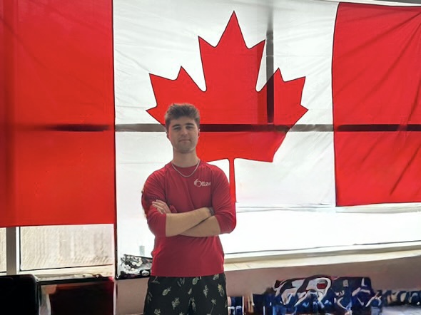
Hi, I'm Jonathan.

I'm a 3rd-year Electrical Engineering student at Carleton University.

Ottawa, ONOpen to relocation
BilingualEnglish & French
About Me

A bit about my interests

Before I was building circuits, I was a certified lifeguard, swim instructor, and first aid instructor with the City of Ottawa, and a volunteer coach for competitive speed skaters. Those roles taught me the same lesson twice: stay calm under pressure, document everything properly, and take responsibility when it counts.

That mindset carries into how I approach engineering. I like taking an idea from a rough sketch to something that actually works. Most of my projects come down to the same cycle: build it, test it until it breaks (I like that part more than I probably should), figure out why, and fix it properly. I am always curious to learn about new technology and have recently developed an interest for AI implementation and use cases, which I am hoping to incorporate into some of my future projects.

I'm always open to co-op opportunities, conversations with other engineers, or just learning how things actually work and get done in the real-world.

Skills

Tools & technical proficiencies

Design & Simulation

  • Altium Designer
  • EasyEDA
  • NI Multisim
  • Vivado
  • Autodesk Fusion CAD

Programming

  • C / C++
  • Python
  • Java
  • Verilog HDL
  • Git Version Control

Hardware

  • Soldering & Rework
  • Oscilloscope / Multimeter
  • 3D Printing & Prototyping
  • Breadboarding
  • Component Analysis

Platforms

  • Arduino
  • Raspberry Pi
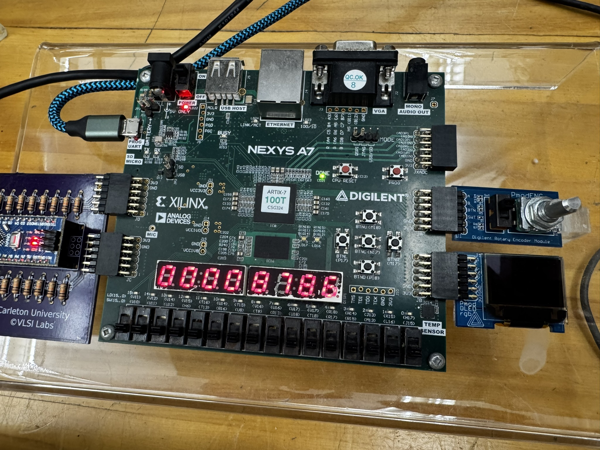
  • FPGA
  • LaTeX
  • Jupyter Notebook
Contact

Let's build something.

I'm currently looking for a 2027 Summer co-op placement. Always happy to talk about a project, a role, or just electronics and technology in general.
โ† Back to projects
PROJ-001 ยท PCB Design

Modular Bicycle Lighting System

2022Timeline
Solo ProjectRole

The Idea

I created a PCB layout for a personal project of mine. The aim was to build a novel, programmable, and controllable RGBW lighting system for my bicycle and electric scooter. The intention was to potentially commercialize the final product, since I felt there weren't any options on the market providing the same functionality.

Prototyping the Idea

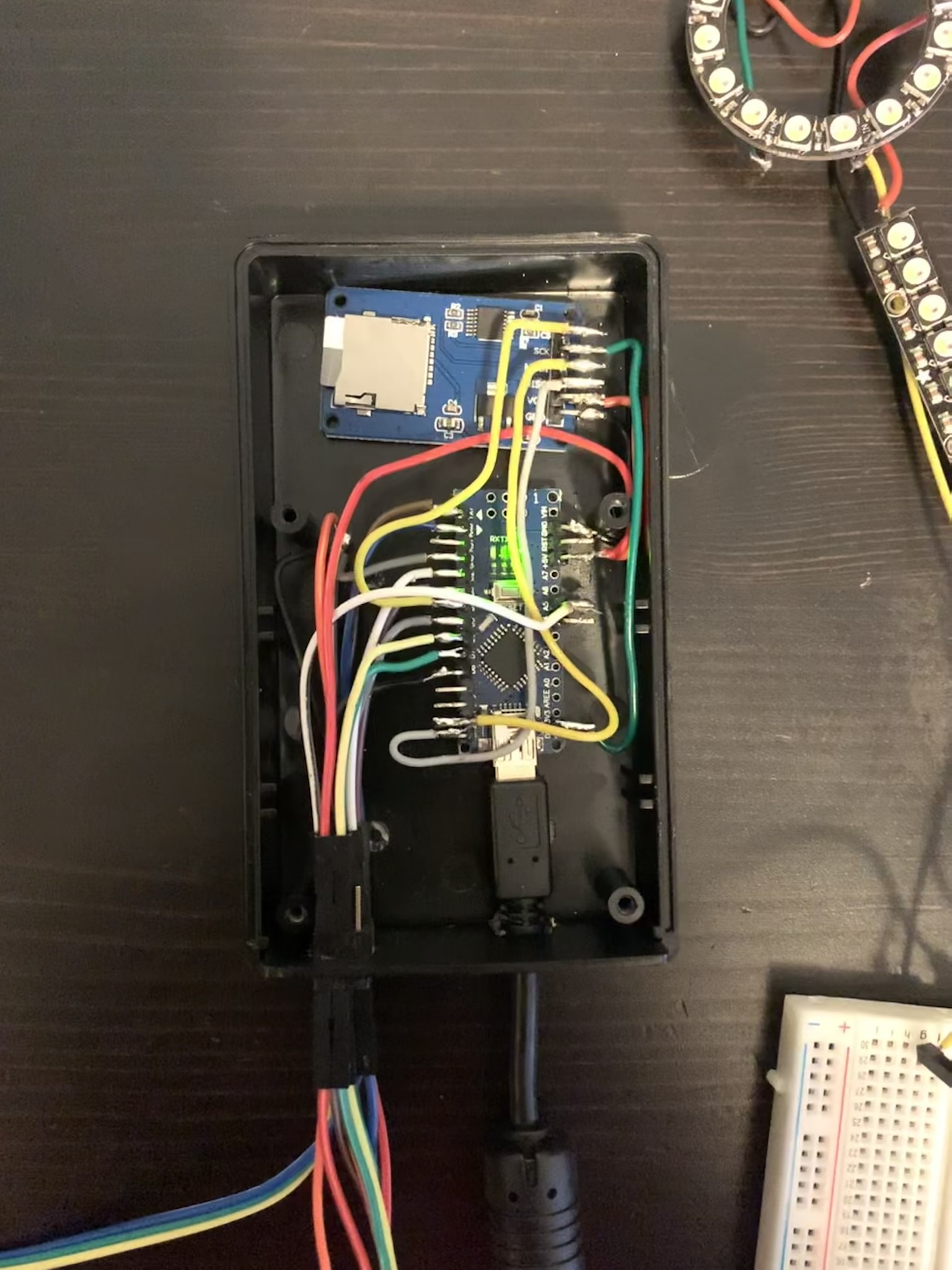
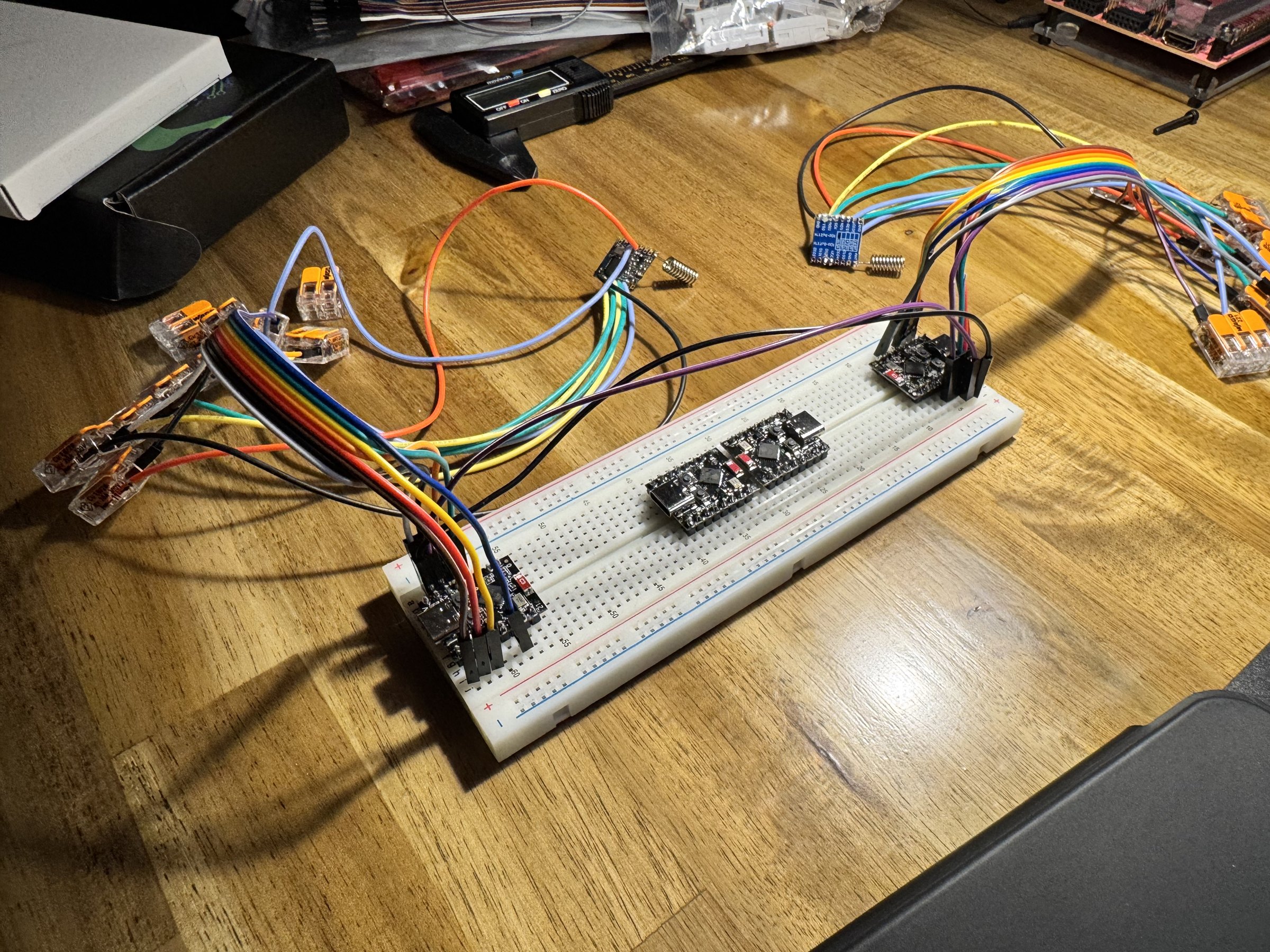
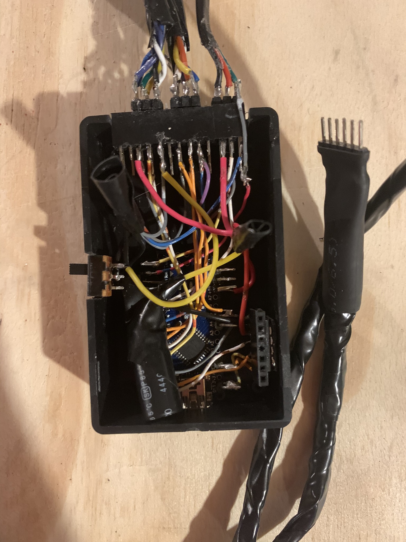
I initially started prototyping with raw wires and generic component boxes. Over a few iterations, I added and removed certain additional functionality, like chimes and signal clicks, along the way once I decided they were unnecessary.

prototype v1
Fig. 1 โ€” Layout V1, first prototype
prototype v2
Fig. 2 โ€” Layout V2, compact circuit

Designing the PCB

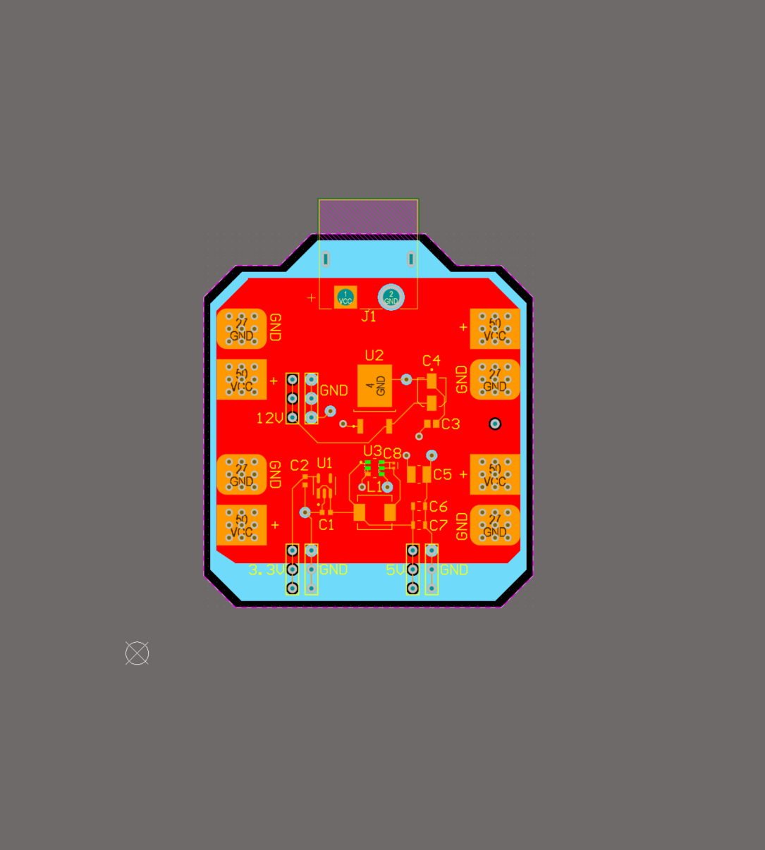
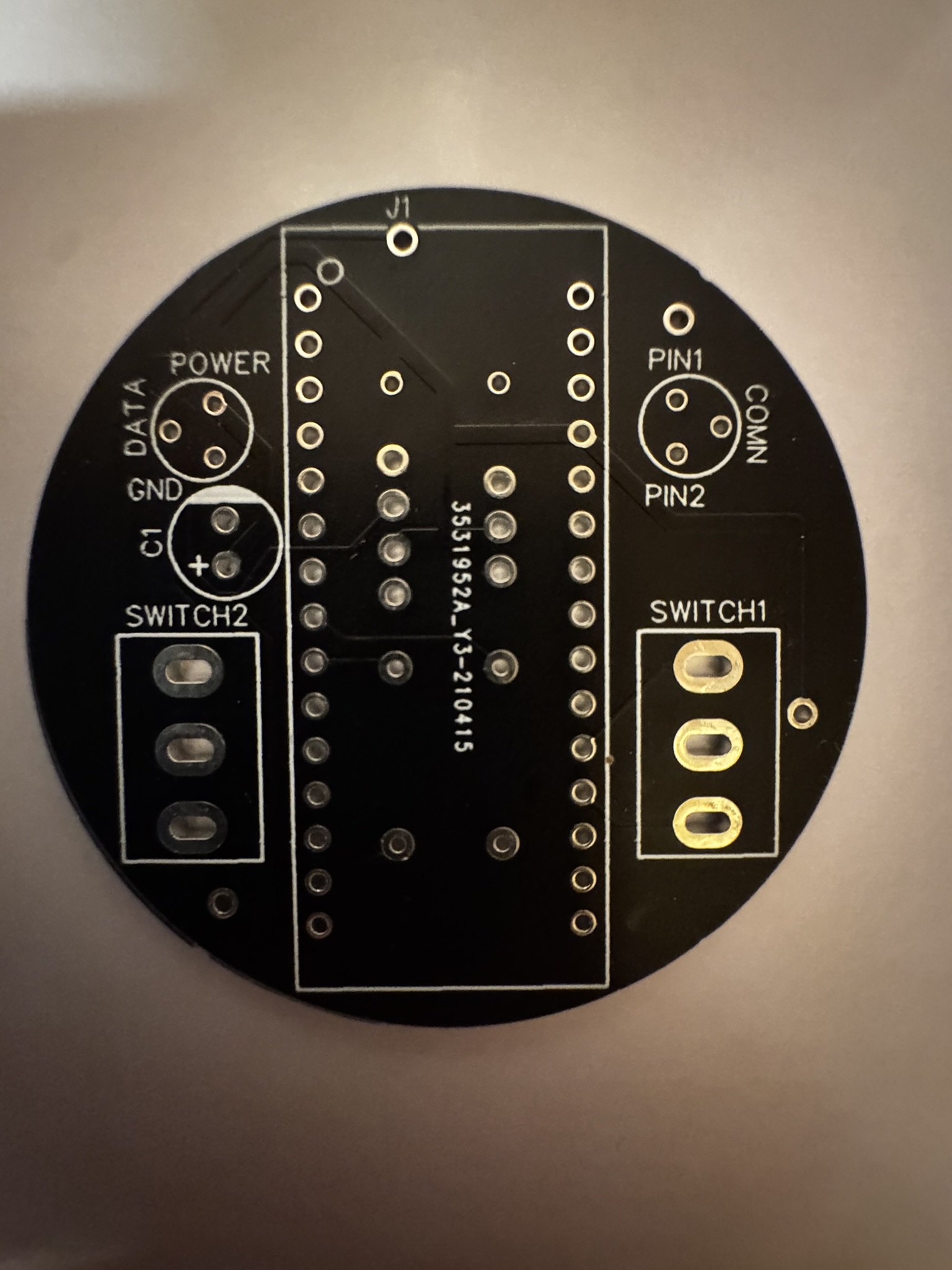
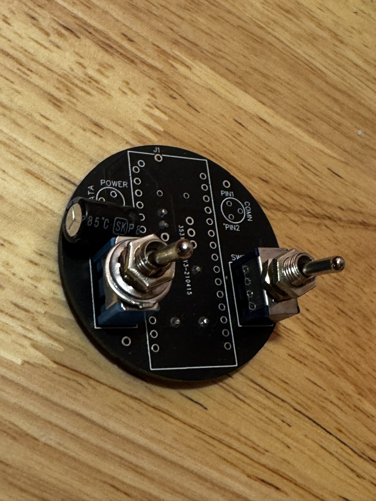
I designed the PCB in EasyEDA to support the control module (an Arduino Nano) and have all the required connections in functional locations for final assembly. This was based on the circuit layout I developed during the prototyping phase. The process involved learning how to use the PCB design interface and researching best practices for vias and hole tolerances for various components. It was useful to cross-reference by measuring pin diameters with a precision caliper at home to make sure no major mistakes were being made.

pcb raw
Fig. 3 โ€” Raw PCB as received
pcb populated
Fig. 4 โ€” Components being added

Assembly & Testing

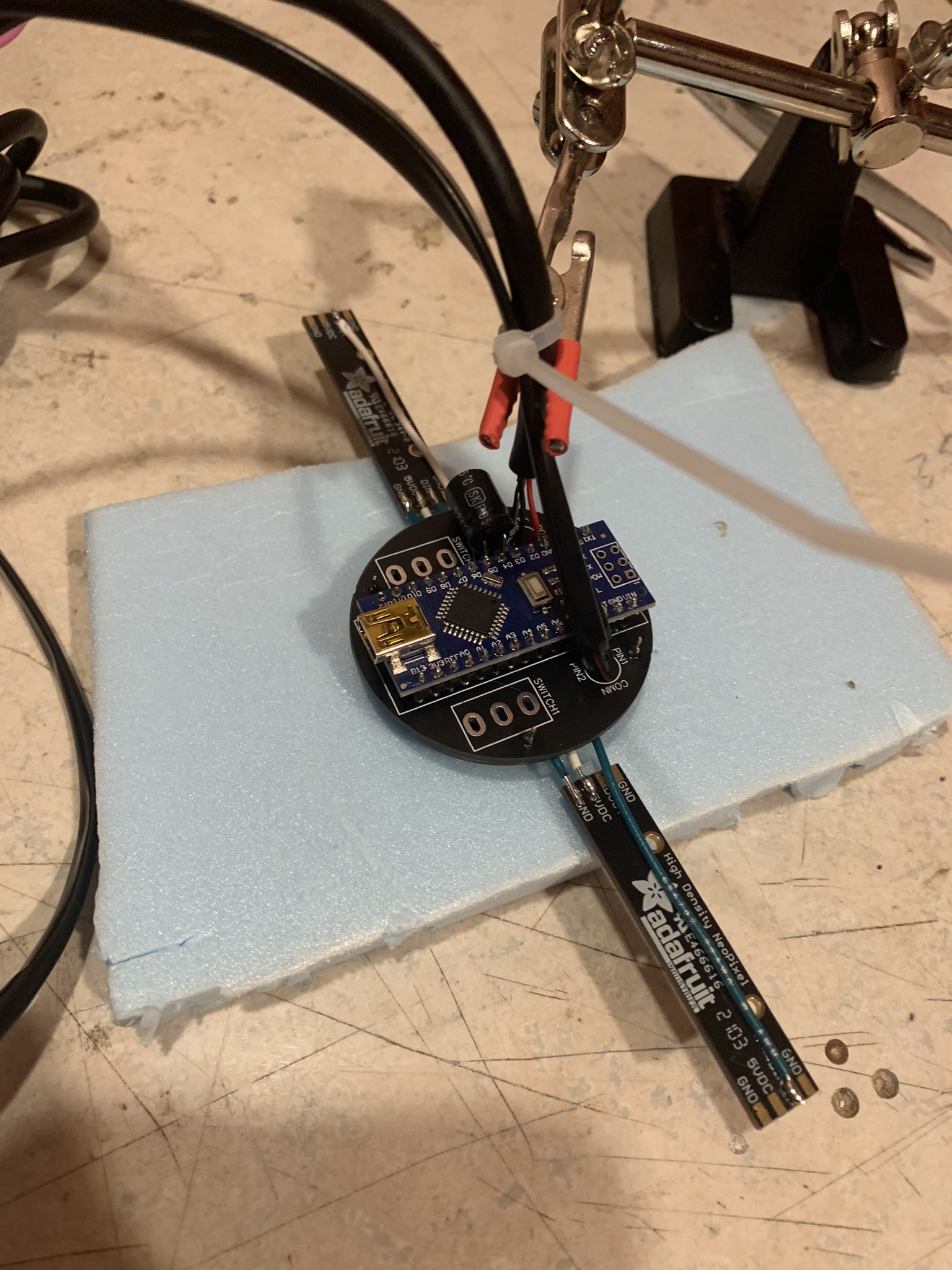
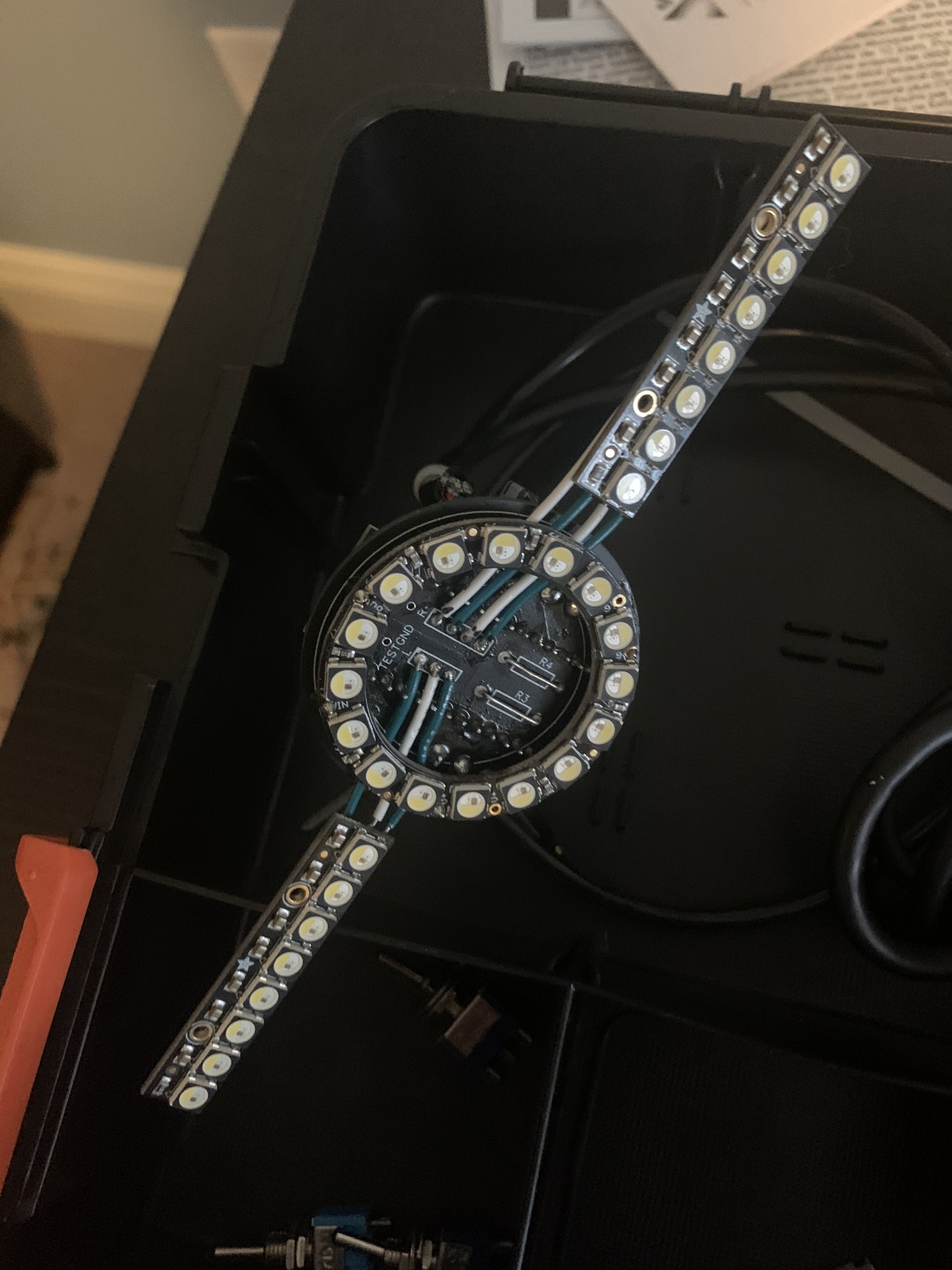
Before combining everything with the 3D printed casings, I ran the assembly through a couple of testing phases. The first pass was missing the physical switches, which I simulated with keystrokes on the Arduino-connected laptop while programming. That stage also included soldering the Adafruit NeoPixel strip boards onto the outer portion of the pixel design. The final circuit shown below includes the real switches and was tested exactly as it would be used on the bike.

final circuit
Fig. 5 โ€” Final circuit assembly on PCB

Hardware & Mounting

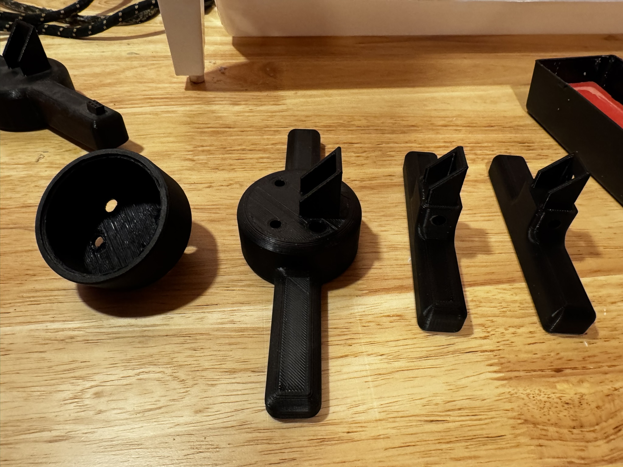
Next, I needed to make sure the system was weatherproof for rainy days and outdoor storage. I designed three different casing models in CAD and 3D printed them for front, rear, and a compact version aimed at scooters or racing bikes. The circular case uses the same PCB as the linear one, though the connections for the side NeoPixel strips are simply left unused on that version.

The design was originally meant to be easy to construct and produce, simple and scalable enough to sell at a reasonably competitive price. I never ended up trying to sell any, mainly due to cost and manufacturing time, even though the final design came close to being a finished product.

casings
Fig. 6 โ€” Different casing designs (front, rear, compact)

Summary and Takeaways

Overall, I really enjoyed working on this project since it gave me immediate, practical benefits: having programmable lighting while biking at night. I was able to take the idea from concept to a final product and made significant improvements in durability and reliability along the way. I also enjoyed working with online development environments and making all of the decisions (and mistakes) that came with PCB and CAD design as a first-time solo designer.

โ† Back to projects
PROJ-002 ยท Power Electronics

MOSFET/Arduino Integration for Vehicle Lighting

2025Timeline
Solo ProjectRole

The Problem

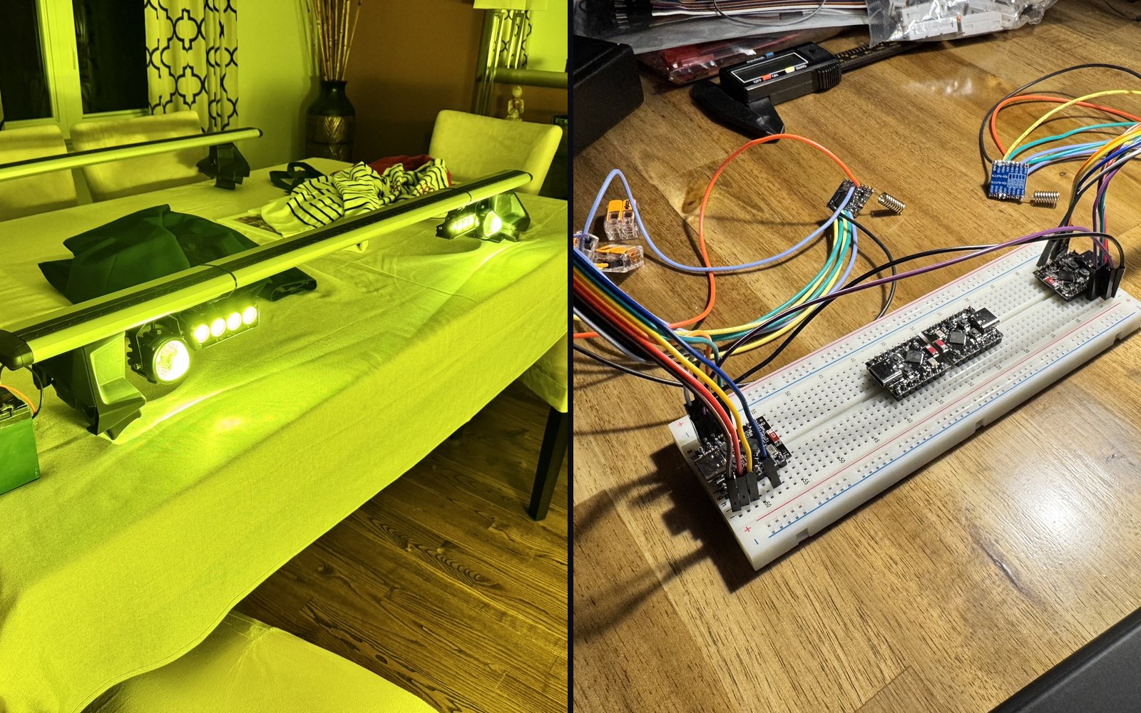
Earlier this year, I wanted to retrofit some high-powered LED lights onto the roof rack of my vehicle. I researched ways to connect this system to an existing Arduino I already had installed in my dash for modular projects like this. I settled on using MOSFET components to act as quick-response relays for flash patterns, connecting the system to a switched fusebox source through the MOSFETs. The whole system is button-controlled via the Arduino, since using a microcontroller let me build more complex rapid flash patterns based on button presses and switch sequences.

Initial Design

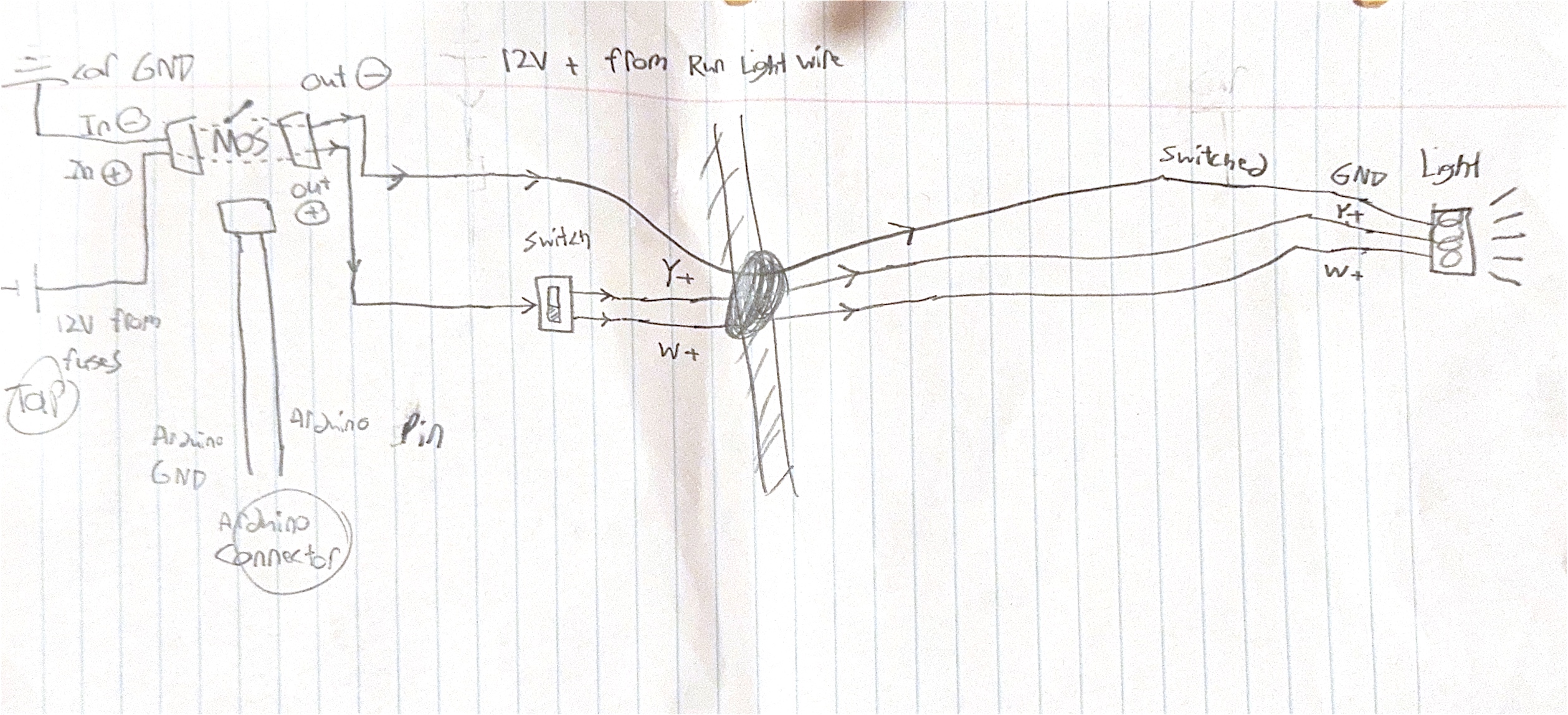
I first designed a rough draft of the circuit on paper based on my research into MOSFETs and Arduino pin control. This served as a template for prototyping the circuit.

hand sketch
Fig. 1 โ€” Hand-drawn sketch of wiring and plan

Prototyping & Testing

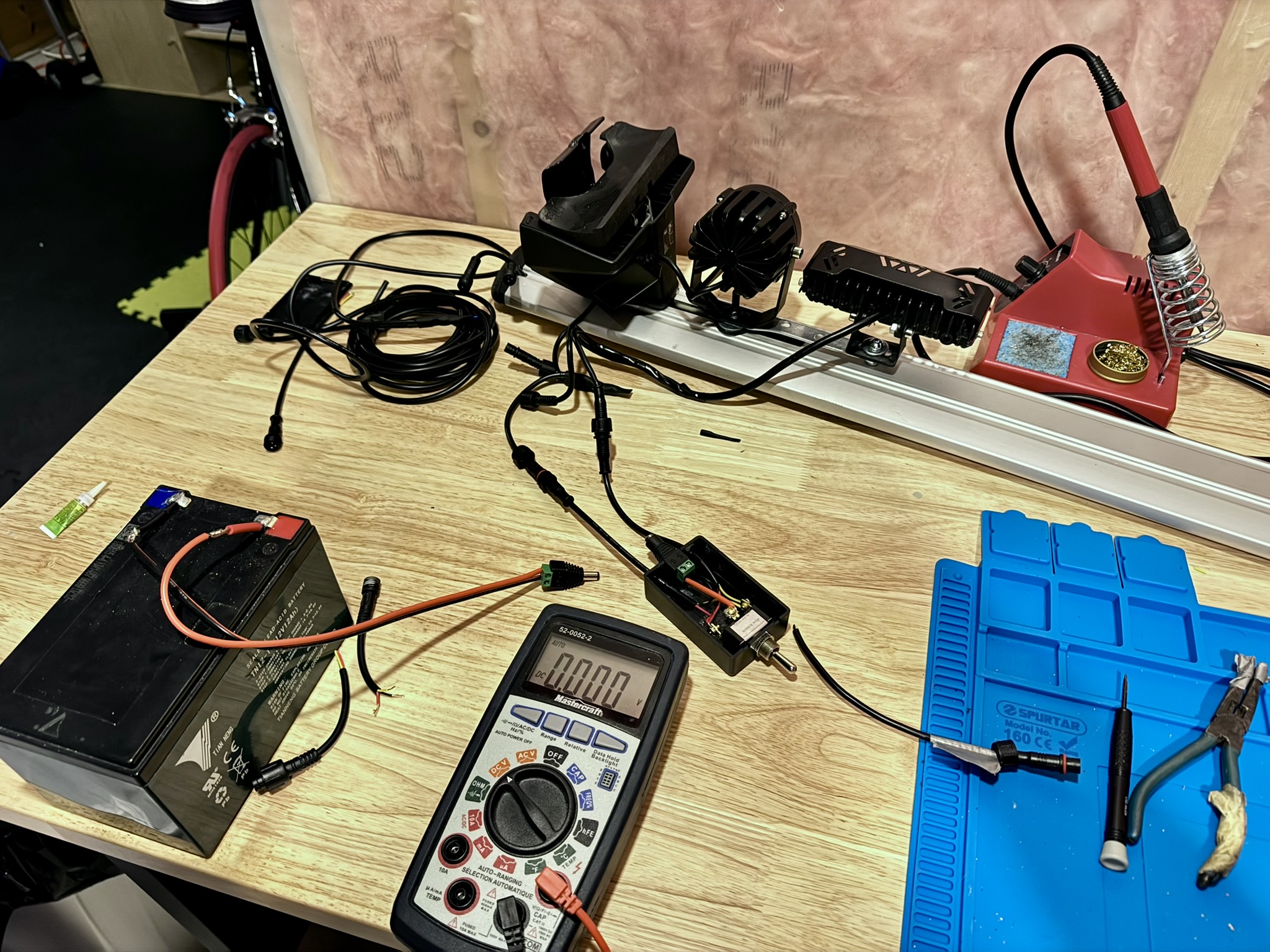
I assembled the design on a breadboard and tested it with a modular power supply to make sure there wouldn't be any issues with overloading or heat dissipation once it was fully installed on the car.

installed lights
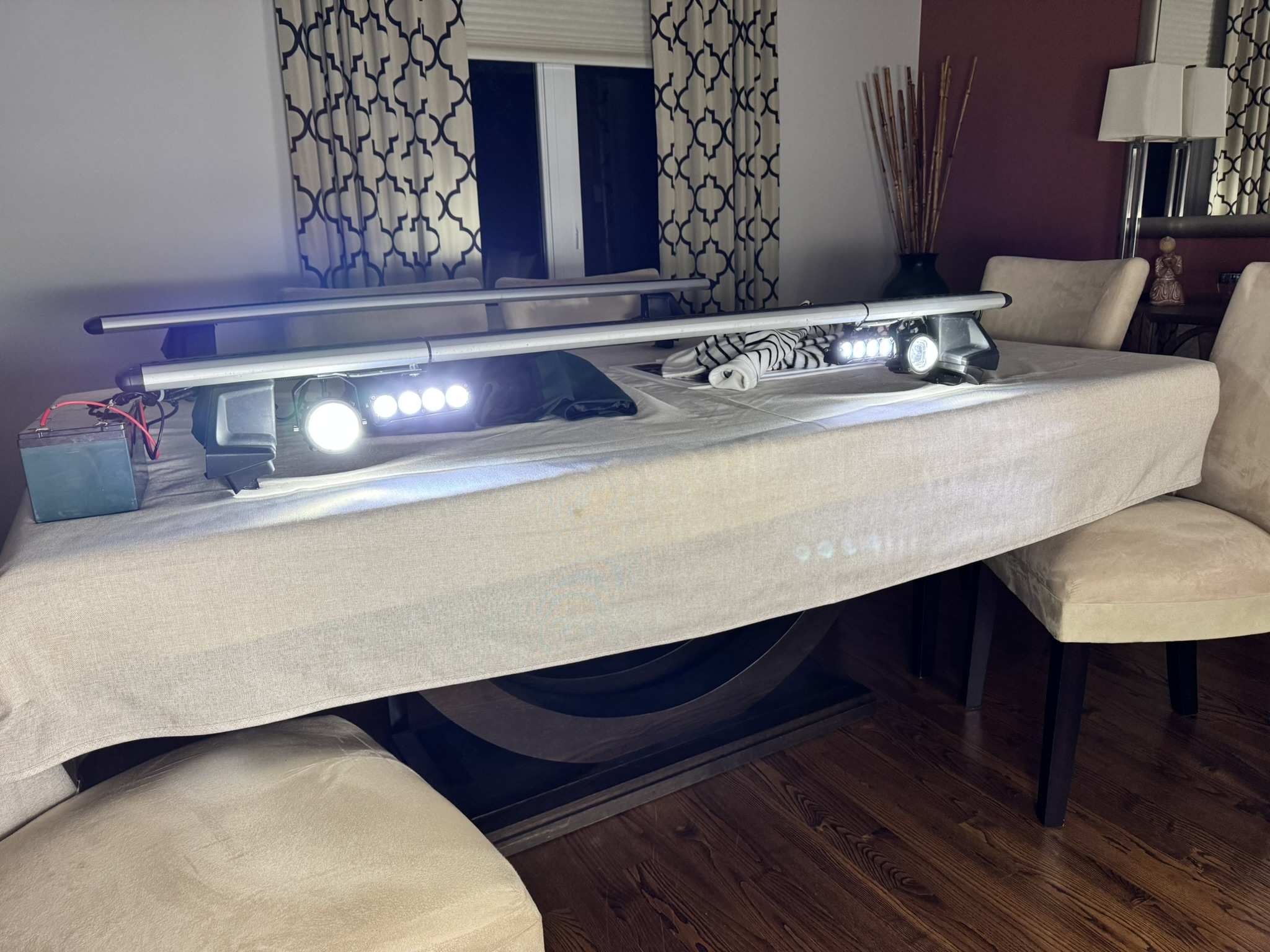
Fig. 2 โ€” Final install, static yellow mode

This project still serves me during the summer months, and I've since tweaked the design to be more easily removable with modular weatherproof connectors that I soldered onto both the car wiring outputs and the roof rack connections.

Summary and Takeaways

With this project I gained valuable hands-on experience designing and building a practical electronics system for my car. It involved learning to design a control system using an Arduino to manage the high-power LED lights and create custom flash patterns. I developed skills in power electronics and interfacing by selecting, testing, and implementing MOSFETs, which turned out to be the best option for my goals. A major takeaway was around prototyping and quality assurance: I started with a rough sketch, built it on a breadboard, and tested it extensively to make sure the components wouldn't overheat or fail in a real-world automotive setting, with internal vehicle temperatures ranging anywhere from -35ยฐC to 40ยฐC in worst-case scenarios. I also learned how to handle automotive electrical systems by safely wiring the finished circuit into the vehicle's existing fusebox with the proper fuses and load resistors.

โ† Back to projects
PROJ-003 ยท Electromechanical

Electric Go-Kart

2019Timeline
2-Person TeamRole

The Idea

An earlier project of mine was inspired by Formula One, when a friend and I wanted to take on the challenge of building a soapbox racing kart just for fun. It quickly evolved into a fully-fledged 1.6kW powered metal machine and taught me a lot about three-phase motor control and manufacturing.

Frame

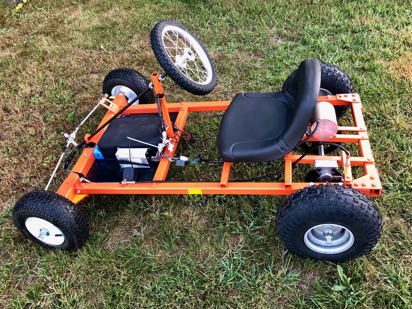
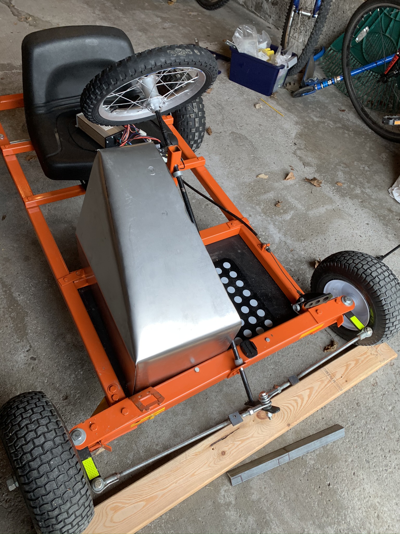
The frame was initially planned out using wood beams cut to size, to check the size and maneuverability of a simple rectangular box with bracing. Once the design was proven to work conceptually, the whole kart was cut from rounded square box-section steel with sheet metal for the flooring. With limited tooling, this proved to be a real challenge even with careful measurement. You can see the repurposed kid's bike wheel below, standing in as a makeshift steering wheel while we tested rolling resistance and steering angles.

frame assembly
Fig. 1 โ€” Mostly assembled frame (with a repurposed kid's bike wheel standing in as the steering wheel during testing)

Power System & Electronics

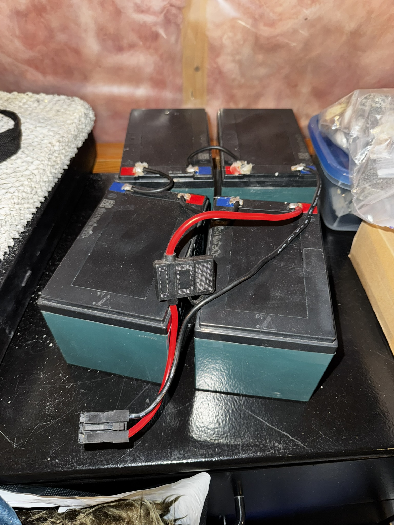
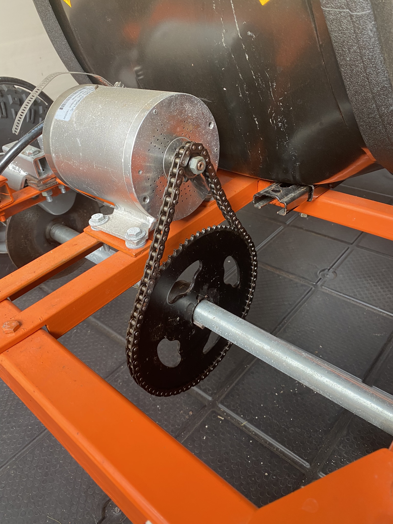
The power system consisted of four 12V lead-acid batteries, generally used for emergency lighting systems, wired in series. These provided the necessary voltage to the 1.6kW-rated motor controller. The motor is normally used for large garage door mechanisms or electric outboard motors for boats, but the mounting plate and torque ratings made it a good fit for this application. The gear ratio was chosen for low-speed pickup and rougher terrain use, since it multiplied the torque almost tenfold. That meant the real challenge became keeping the motor running near its max RPM and current rating for any mid to high-speed cruising at that gear ratio, and we ran into plenty of issues with chain tensioning and brackets bending under heavy acceleration.

battery pack
Fig. 2 โ€” Assembled battery pack
motor assembly
Fig. 3 โ€” Motor assembly

I ended up having to research and swap out the actuator pedal for the motor controller so it had a larger analog travel range. The original one was nearly impossible to map into smooth RPM increase, even with a lot of practice, and since there was no way to reprogram the controller itself, replacing the pedal was the easiest fix for the jerky acceleration.

Final Result

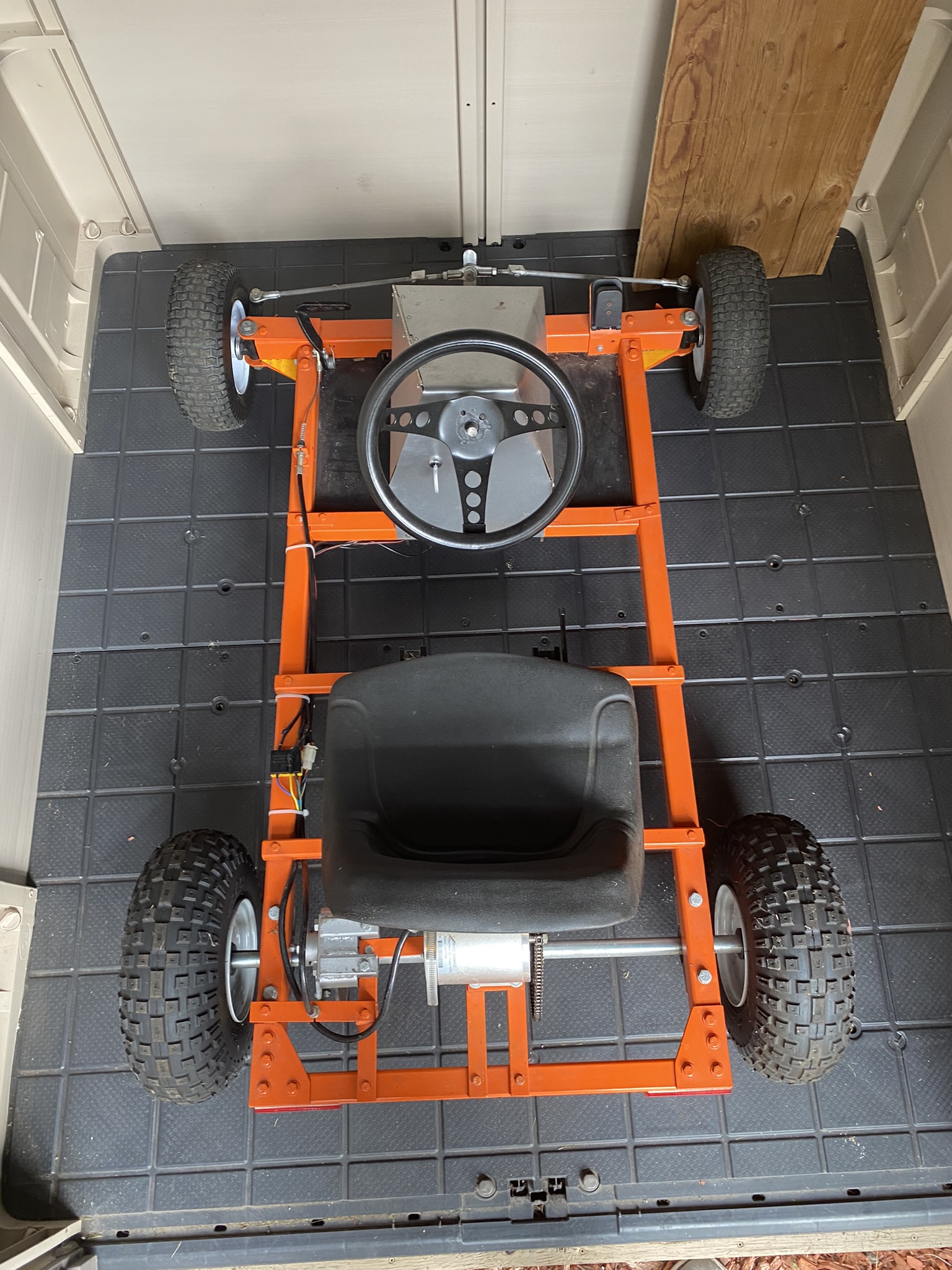
With the electronic controls in place and some torque and power delivery optimizations, my friend managed to hit 49 km/h in a straight-line test on paved road, not bad for a build carrying a 200+ lb driver. Under more regular use, like cruising around neighborhoods and parks, the 15 Ah battery pack gave us 3 to 5 hours of stop-and-go runtime. We looked into adding regenerative braking to recharge the battery as a generator, but it quickly became clear the extra three-phase battery control hardware needed would blow past our budget.

final gokart
Fig. 4 โ€” Final construction

Summary and Takeaways

The Go-Kart project was one of the first times I combined my interest in mechanical design and fabrication with my fascination for electronics and electrical systems. It took a lot of labour to put together, but it was well worth it. Troubleshooting the throttle sensitivity and power delivery issues taught me a lot about trial-and-error problem solving, and it's honestly the project that pointed me toward electrical engineering in the first place.

โ† Back to projects
PROJ-004 ยท Avionics

Twin-Engine RC Aircraft (P-38 Lightning)

OngoingTimeline
Electronics TeamRole

The Project

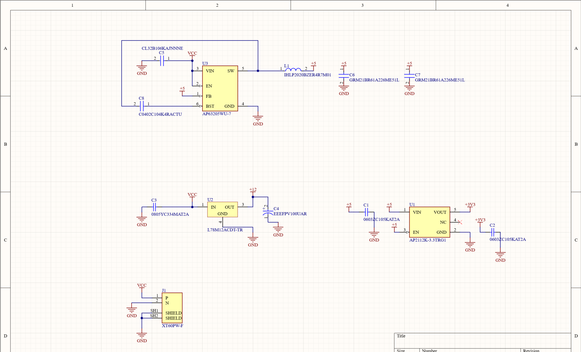
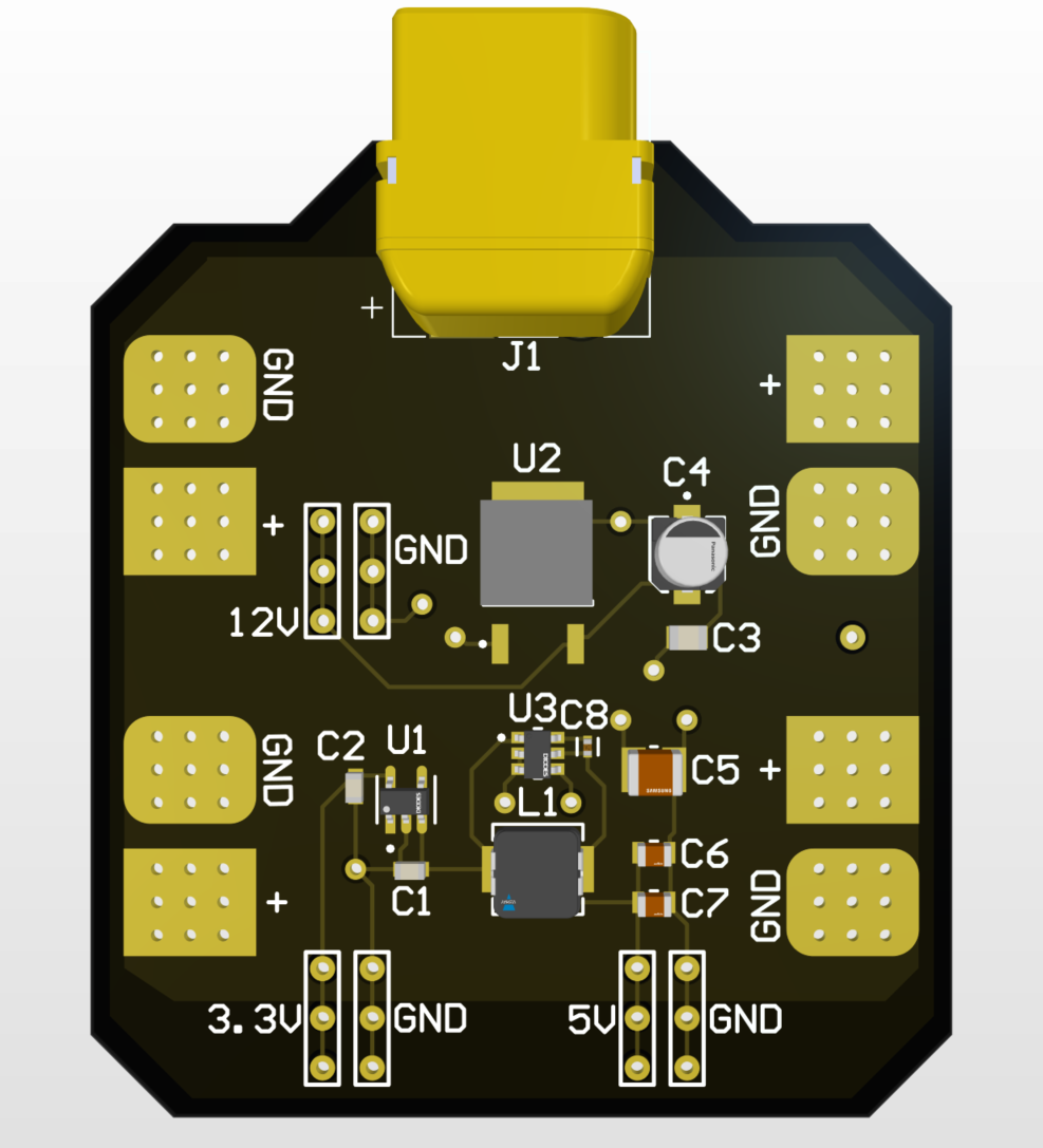
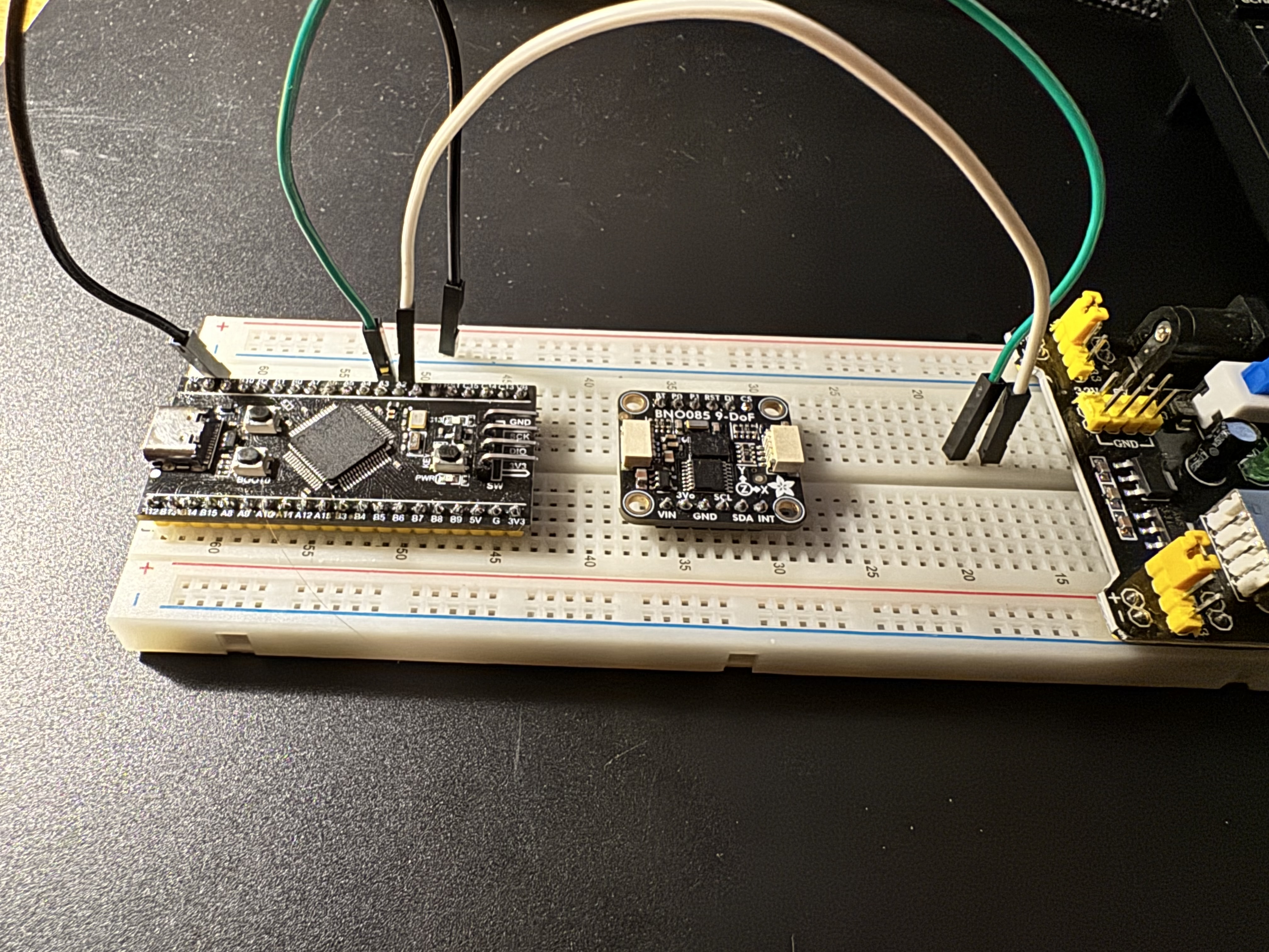
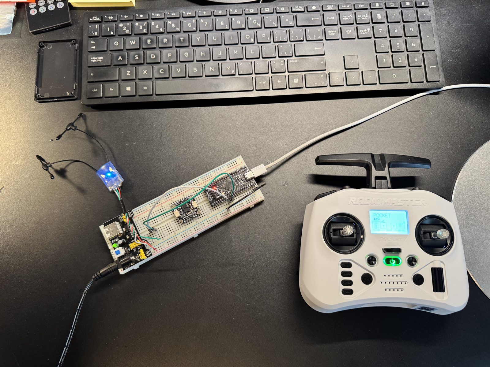
I'll be joining the electronics subteam on a twin-engine RC aircraft build. Our subteam is four people, including me, working within a larger project team of around eight to nine people total. My focus is on designing the flight controller around an STM32, the RF transmission and reception system, and some basic GPS and autonomous flight capability.

Looking Ahead

This project is still early, so a lot of the specific component choices and architecture decisions are still ahead of us. The first concrete deliverable will be a full bill of materials, which I'll add here as a photo once it's finalized. From there, I'm hoping to also share some of the flight controller code on GitHub and, if the timeline allows, a 3D model of the PCB itself.

โ† Back to projects
PROJ-005 ยท Software & AI

AI Agent Setup

2026Timeline
Solo ProjectRole

Overview

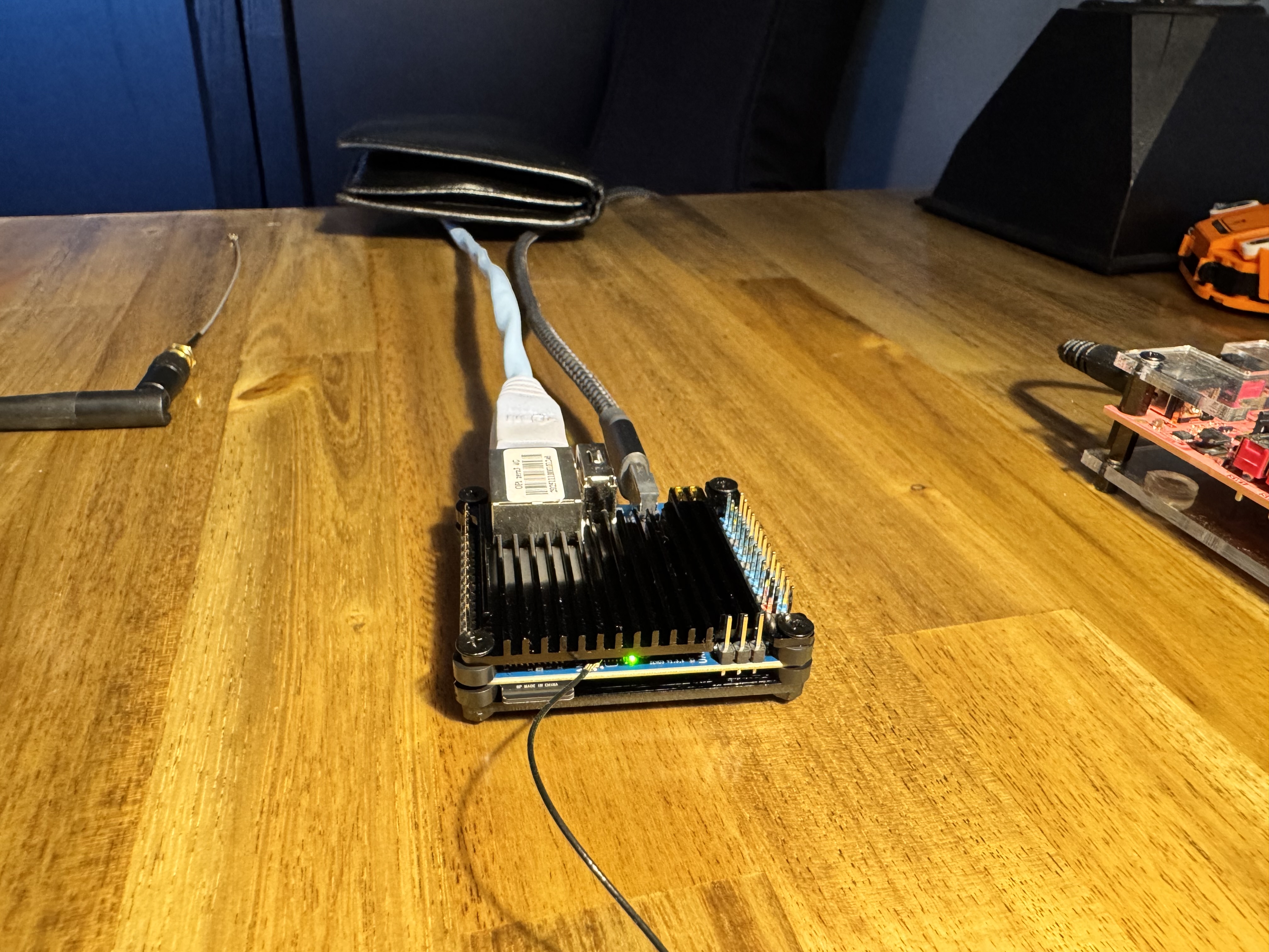
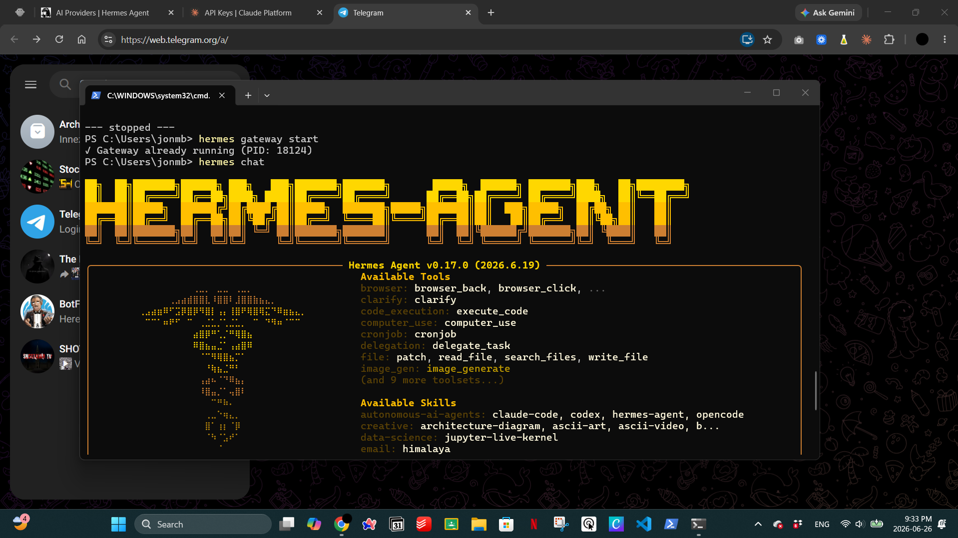
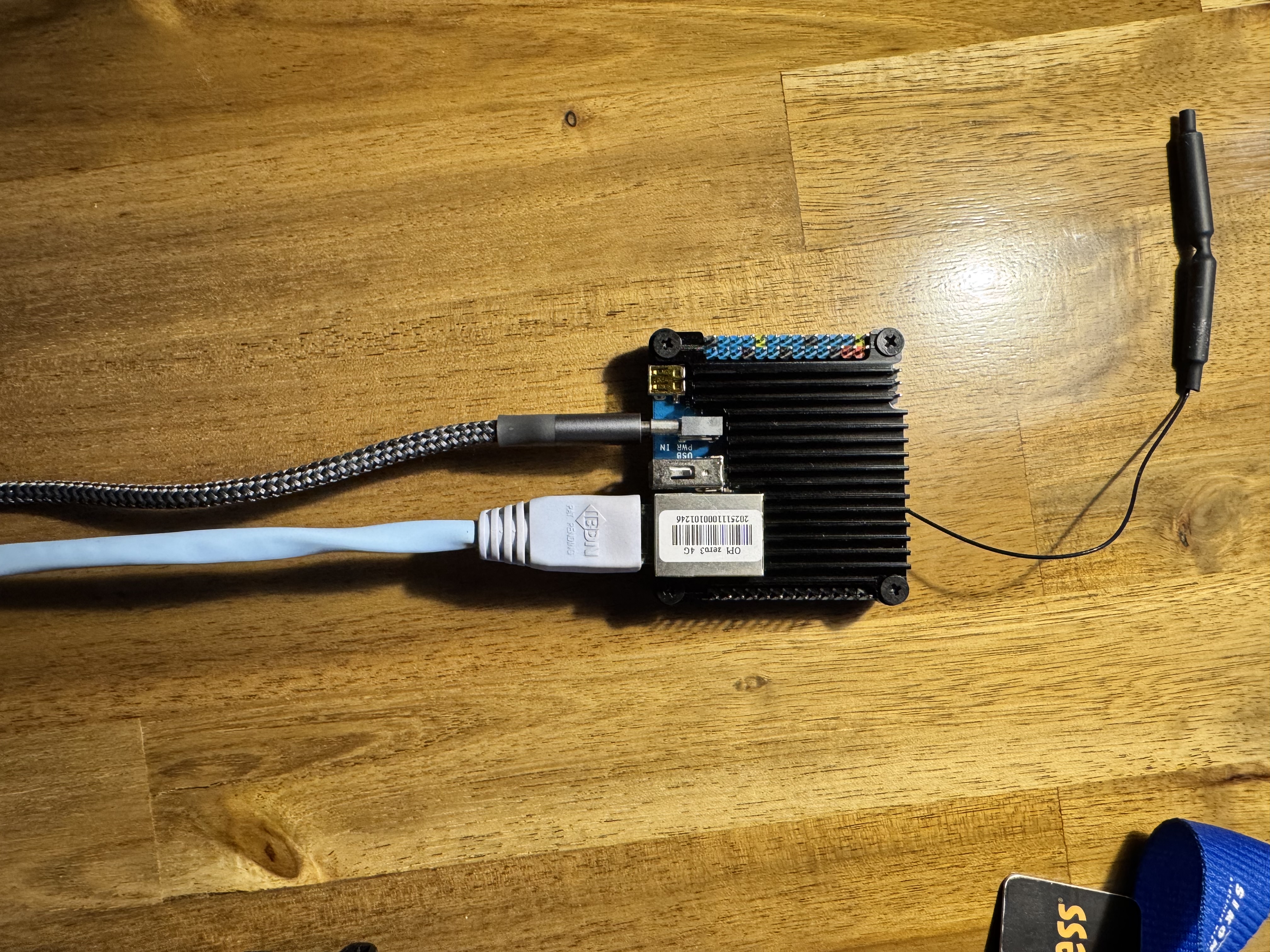
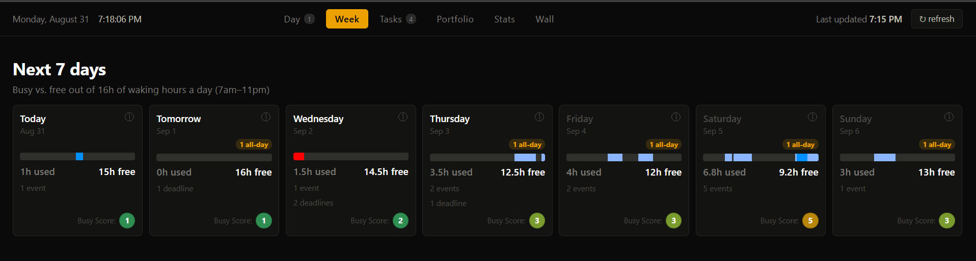
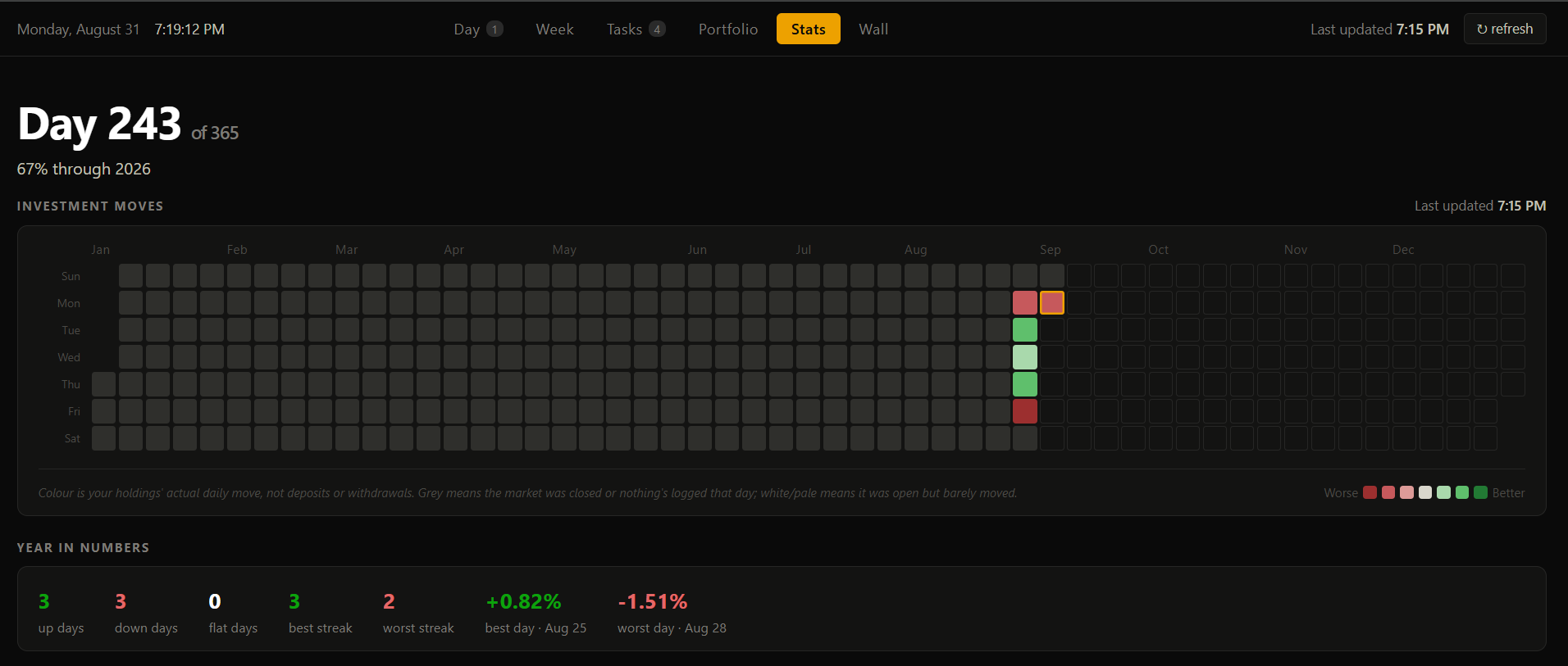
I installed and configured Hermes, a self-hosted AI agent, setting up its plugins and markdown configuration files to fit the tasks I actually wanted automated day to day. As a first real use case, I interfaced the Yahoo Finance and Telegram APIs to build a simple daily investment update: the agent checks my watchlist each day and sends a summary straight to Telegram, so I can check it without opening a separate app or dashboard.

agent demo
Fig. 1 โ€” Agent in action

Looking Ahead

This is an early, ongoing project. I'm looking to build out more automations as I find genuinely useful daily tasks worth handing off to it.